The transmit audio path (simplified):
Mic --> CODEC --> FPGA --> Ethernet (digitized audio data) --> PC (PowerSDR mRX audio processing and modulation) --> Ethernet (digitized IF data) --> FPGA --> DAC --> RF Amplifier --> Antenna
The receive audio path (simplified):
Antenna --> ADC --> FPGA --> Ethernet (digitized IF data) --> PC (PowerSDR mRX demodulation and audio processing) --> Ethernet (digitized audio data) --> FPGA --> CODEC --> Speaker or Headphones
Not as simple as you though, eh?
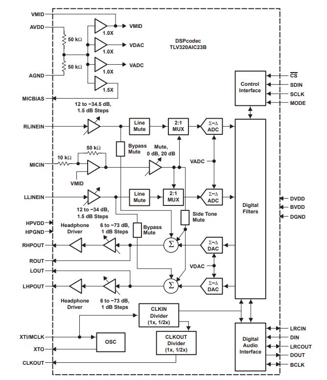
Another excellent document to look at is the data sheet for the Texas Instruments TLV320AIC23B CODEC integrated circuit (attached to this post). If you review that, and also take a look a the various board schematics, you will see that the user interface in PowerSDR, both the main console and in Setup > Transmit, gives nearly direct control over the various settings of that CODEC. Unfortunately not all functions are made available, most notably sidetone, but they are in there if anyone ever decides to write the software/firmware necessary to exploit them. It should be noted that the choice of input resistors (the same in all ANAN series radios) on the mic input set the mic gain to approx. 3.5 (5.4dB). The data sheet, on Page 1-5, says that the mic bias voltage is 3/4 AVDD nominal. On the schematic, AVDD is 3.3VDC. So that would make the mic bias voltage approx. 2.5VDC, and this is delivered to the microphone via a 3.3K series resistor.