Page 1 of 1
Band decoder tor Anan
Posted: Sat Jul 03, 2021 1:24 pm
by oe3ide
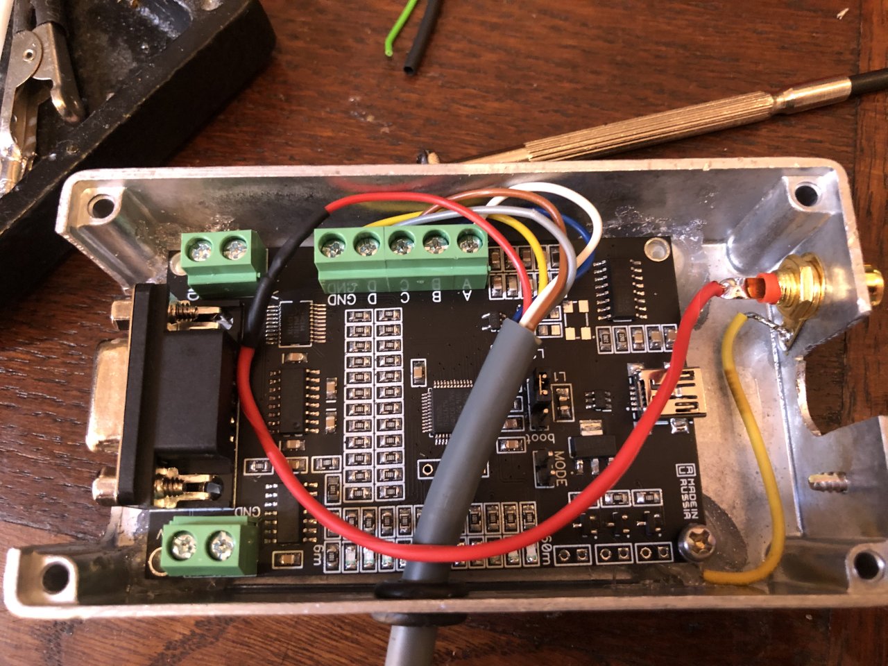
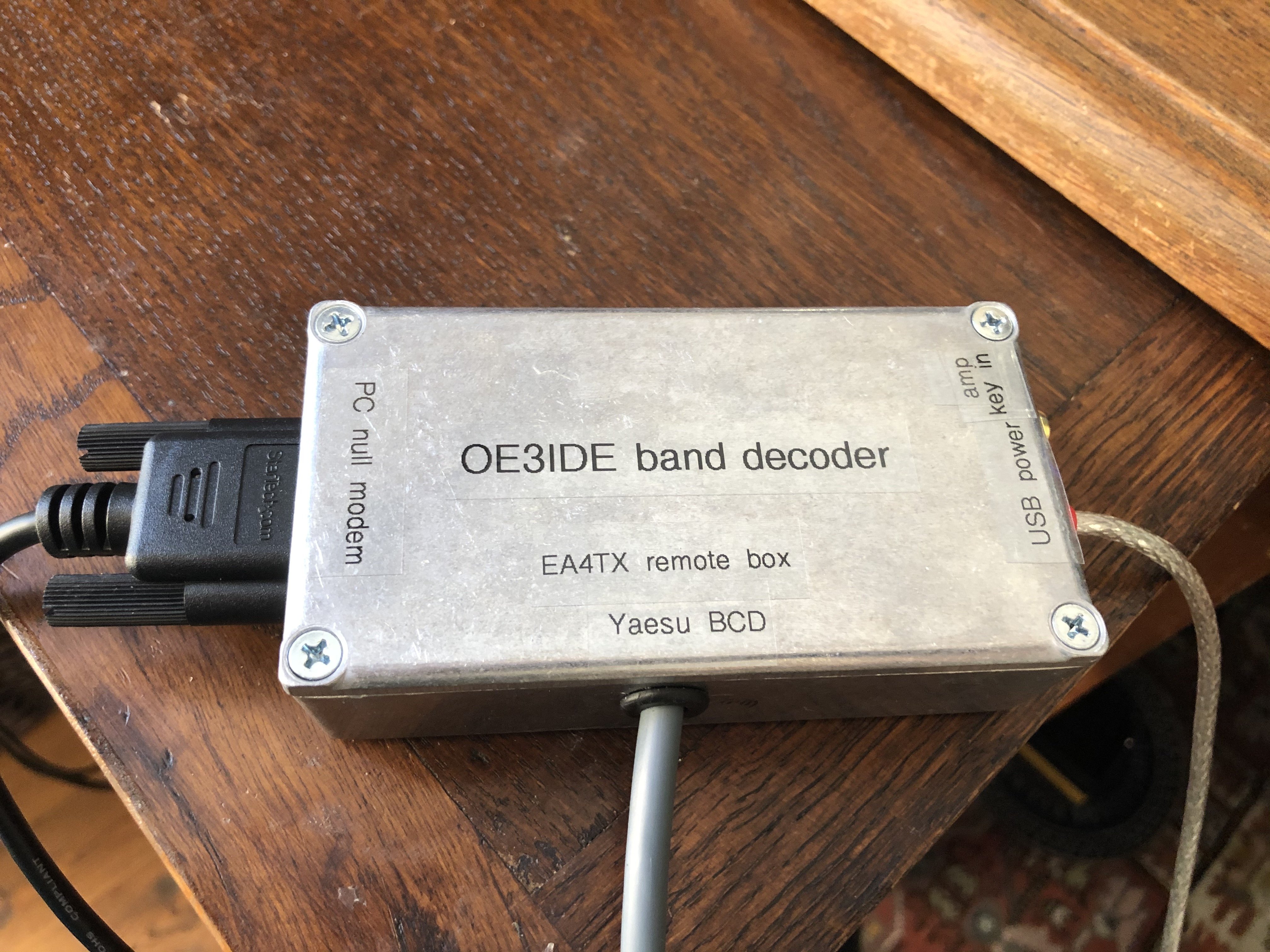
Just finished my last little project. I have a remote antenna switch from EA4TX. The controller is accepting band data in Yaesu and Icom format.
The universal band decoder converts the regular Kenwood cat-data into BCD or Icom Voltage band data. So the RS232 is connected to the PC (COM5). In Thetis I have activated this com port.
The decoder polls every 500ms (sending "IF;") and sends the band data to the EA4TX-Controller. Amp-key-in is for protecting against hot-switching.
73 Ernst
OE3IDE
- oe3ide-band-decoder2.jpg (241.22 KiB) Viewed 10357 times
- oe3ide-band-decoder1.jpg (1.84 MiB) Viewed 10357 times
Re: Band decoder tor Anan
Posted: Sun Jul 04, 2021 8:52 am
by EA1DAV
Hi Ernst, I do the same with the Open Colector out in the back of my 100D and the 6x2 EA4TX box. Pull up resistor needed.
73, ea1dav
Re: Band decoder tor Anan
Posted: Sun Jul 04, 2021 9:15 am
by oe3ide
Hi,
Yes, I also considered using OC. But I wanted to be independent of the Anan hardware, which is why I chose the Cat interface.
73 Ernst
Re: Band decoder tor Anan
Posted: Mon Oct 31, 2022 11:25 pm
by K4IBC
Hello Ernst,
I was searching for a hardware solution to interfacing to my Icom PW-1 and came across this interface.
It appears it would take Kenwood serial data and convert it to Icom CIV data. Is this true?
I found the guys website and eBay listing but unfortunately he doesn't sell to the U.S.
Re: Band decoder tor Anan
Posted: Tue Nov 01, 2022 7:59 am
by oe3ide
Hi,
exact. It takes Kenwood protocol and puts out Icom Band voltage or BCD (Yaesu).
73 Ernst
Re: Band decoder tor Anan
Posted: Tue Nov 01, 2022 1:46 pm
by K4IBC
Thanks Ernst,
I was able to get in touch with Anton and ordered a couple of converters. Trying to make this as automatic as possible for the PW1. I am getting old and forgetful. I know I could have done it thru additional software or manually but that left too many points of failure.
Re: Band decoder tor Anan
Posted: Sun Dec 25, 2022 6:45 pm
by K4IBC
Got a nice Christmas gift in the mail yesterday. The converters arrived here in the states in just about 8 weeks. Not too bad considering.
I do have a question about a couple of things I am noticing on the board. There in a 4 pin solder pad near the cpu. No documentation I can find mentions it and not on the schematic. Also near the USB connector is two areas which look like solder jumper pads. Any clue what they are for?
The with/without Mode Logger jumper. Is it simply a means to disable date on the USB jack?
Unfortunately I didn't realize he used a mini USB connector and I don't have a cable to fit. I will have to wait to test it.
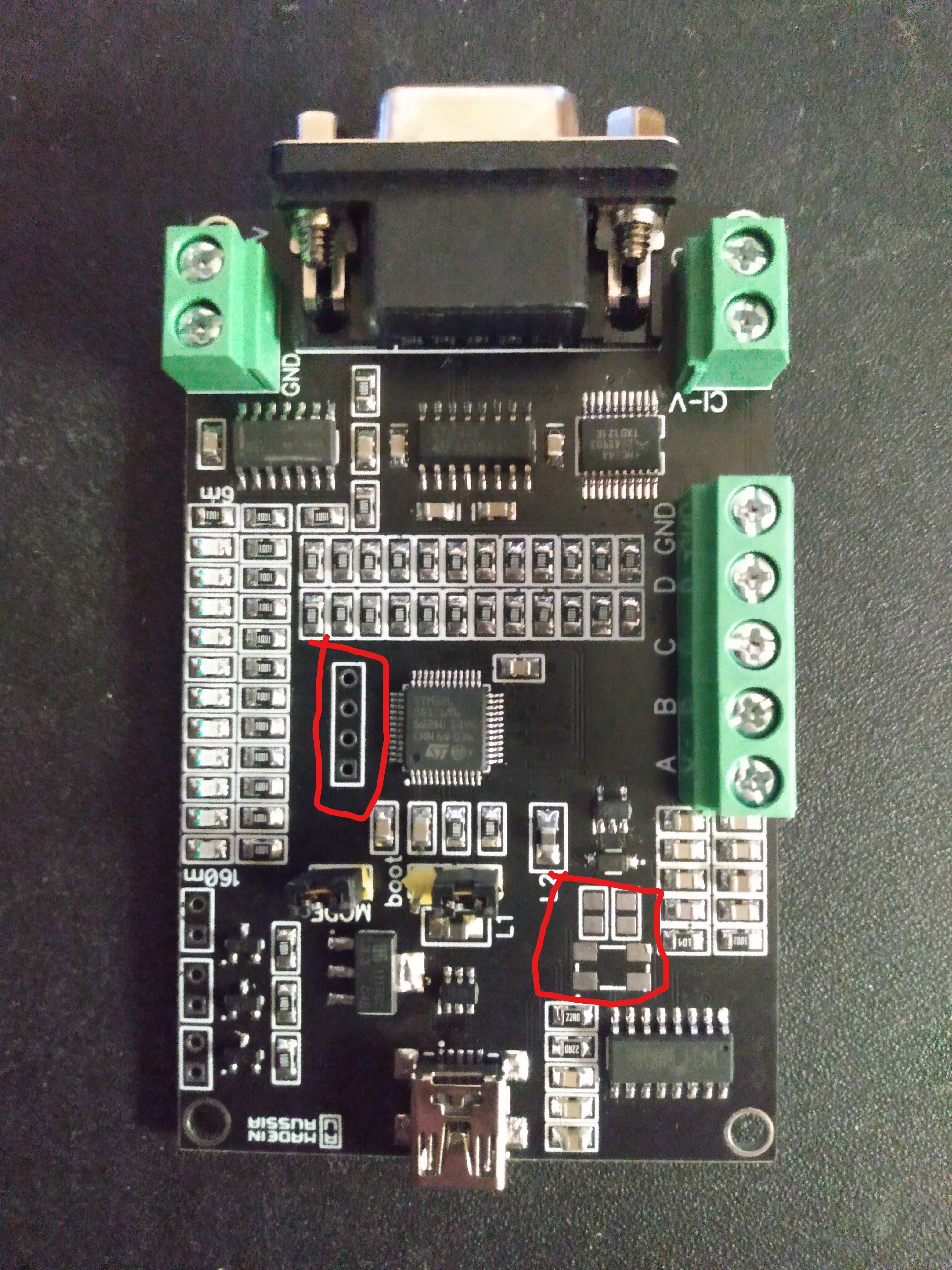
- IMG_20221224_164134985 (3).jpg (4.41 MiB) Viewed 8872 times